Closed-Loop Overview
Closed-loop control typically refers to control of a motor that relies on sensor data to adjust based on error. Systems/mechanisms that rely on maintaining a certain position or velocity achieve this state using closed-loop control. This is achieved by feedback (PID) and feedforward control. Closed-loop control can be performed on the robot controller or on the individual motor controllers. The benefits of onboard closed-loop control are that there is no sensor latency, and the closed-loop controller has a 1 kHz update frequency. This can result in a more responsive output compared to running the closed-loop on the robot controller.
Since closed-loop control changes based on the dynamics of the system (velocity, mass, CoG, etc.), closed-loop relies on PID and feedforward parameters. These parameters are configured either via Tuner Configs or in code. The parameters can be determined using System Identification (such as with WPILib SysId) or through manual tuning.
Manual tuning typically follows this process:
Set all gains to zero.
Select the appropriate Static Feedforward Sign for your closed-loop type.
Increase \(K_s\) until just before the motor moves.
If using velocity setpoints, increase \(K_v\) until the output velocity closely matches the velocity setpoints.
Increase \(K_p\) until the output starts to oscillate around the setpoint.
Increase \(K_d\) as much as possible without introducing jittering to the response.
All closed-loop control requests follow the naming pattern {ClosedLoopMode}{ControlOutputType}. For example, the VelocityVoltage control request performs a velocity closed-loop using voltage output.
Choosing Output Type
The choice of control output type can affect the reproducibility and stability of the closed-loop control.
DutyCycle has the benefit of being the simplest control output type, as it is unaffected by voltage and current measurements. However, because DutyCycle represents a proportion of the supply voltage, changes in battery voltage can affect the reproducibility of the control request.
Voltage control output takes into account the supply voltage to ensure its voltage output remains consistent. As a result, Voltage control often results in more stable and reproducible behavior compared to DutyCycle control, so Voltage control is often preferred.
A disadvantage with both DutyCycle and Voltage control output types is that they control acceleration indirectly and require a velocity feedforward \(K_v\) to hold a constant velocity. On the other hand, torque-based control output types, such as TorqueCurrentFOC, directly control acceleration, which has several advantages:
Since the torque request is directly proportional to acceleration, \(K_v\) is generally unnecessary. A torque output of 0 corresponds to a constant velocity, assuming no external forces.
\(K_a\) can be tuned independently of all the other closed-loop gains by comparing the measured acceleration with the requested acceleration.
Because the output is in units of torque, the units of the gains more closely match those of forces in the real world.
As a result, torque-based control output types offer more stable and reproducible behavior that can be easier to tune compared to the other control output types.
Gain Slots
It may be useful to switch between presets of gains in a motor controller, so the TalonFX supports multiple gain slots. All closed-loop control requests have a member variable Slot that can be assigned an integer ID to select the set of gains used by the closed-loop. The gain slots can be configured in code using Slot*Configs (Java, C++, Python) objects.
Gravity Feedforward
The gravity feedforward \(K_g\) is the output necessary to overcome gravity, in units of the control output type. Phoenix 6 supports the two most common use cases for \(K_g\)—elevators and arms—using the GravityType config in the gain slots.
Elevator/Static
For systems with a constant gravity component, such as an elevator, \(K_g\) adds a constant value to the closed-loop output. To find \(K_g\), determine the output necessary to hold the elevator at a constant height in open-loop control.
Arm/Cosine
For systems with an angular gravity component, such as an arm, the output of \(K_g\) is dependent on the cosine of the angle between the arm and horizontal. The value of \(K_g\) can be found by determining the output necessary to hold the arm horizontally forward.
Since the arm \(K_g\) uses the angle of the arm relative to horizontal, the Talon FX often requires an absolute sensor whose position is 1:1 with the arm, and the sensor offset and ratios must be configured.
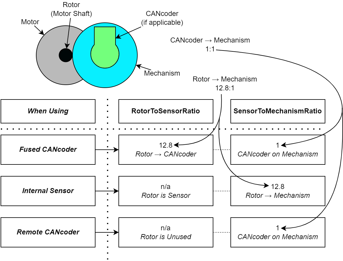
When using an absolute sensor, such as a CANcoder, the sensor offset must be configured such that a position of 0 represents the arm being held horizontally forward. From there, the RotorToSensor ratio must be configured to the ratio between the absolute sensor and the Talon FX rotor.
Some arm mechanisms have a center of gravity that is offset from the zero position. The GravityArmPositionOffset config can be adjusted to account for this offset within ±0.25 rotations.
Static Feedforward Sign
The static feedforward \(K_s\) is the output needed to overcome the system’s static friction, in units of the control output type. Because friction always opposes the direction of motion, the sign of \(K_s\) also depends on the direction of motion. Phoenix 6 provides two possible methods of determining this signage using the StaticFeedforwardSign config in the gain slots.
Velocity Sign
By default, the signage of \(K_s\) is determined by the signage of the velocity setpoint. In other words, if the velocity setpoint is positive, then the output of \(K_s\) is positive; if the velocity setpoint is negative, then \(K_s\) is negative. This option is always used when running velocity closed loops, and it is recommended for Motion Magic® controls and motion-profiled position closed loops.
Closed-Loop Sign
When using a position closed-loop controller, signage of \(K_s\) can instead be determined by the sign of the closed-loop error. For example, if the position error (target - measured) is positive, then the output of \(K_s\) is positive; if the error is negative, then \(K_s\) is negative. This option is typically used when a velocity setpoint is otherwise not available, such as when running unprofiled position closed loops.
Important
When using the sign of closed-loop error for \(K_s\), it is important that the selected \(K_s\) value is not too large. Otherwise, the motor output may dither or oscillate when near the closed-loop target.
Converting from Meters
In some applications, it may be useful to translate between meters and rotations. This can be done using the following equation:
where meters is the target in meters, wheelRadius is the radius of the wheel in meters, and gearRatio is the gear ratio between the output shaft and the wheel.
This equation also works with converting velocity from m/s to rps or acceleration from m/s² to rps/s.
Continuous Mechanism Wrap
A continuous mechanism is a mechanism with unlimited travel in any direction, and whose rotational position can be represented with multiple unique position values. Some examples of continuous mechanisms are swerve drive steer mechanisms or turrets (without cable management).
ContinuousWrap (Java, C++, Python) is a mode of closed loop operation that enables the Talon to take the “shortest path” to a target position for a continuous mechanism. It does this by assuming that the mechanism is continuous within 1 rotation.
For example, if a Talon is currently at 2.1 rotations, it knows this is equivalent to every position that is exactly 1.0 rotations away from each other (3.1, 1.1, 0.1, -0.9, etc.). If that Talon is then commanded to a position of 0.8 rotations, instead of driving backwards 1.3 rotations or forwards 0.7 rotations, it will drive backwards 0.3 rotations to a target of 1.8 rotations.
Note
The ContinuousWrap config only affects the closed loop operation. Other signals such as Position are unaffected by this config.
In order to use this feature, the FeedbackConfigs (Java, C++, Python) ratio configs must be configured so that the mechanism is properly described. An example is provided below, where there is a continuous mechanism with a 12.8:1 speed reduction between the rotor and mechanism.